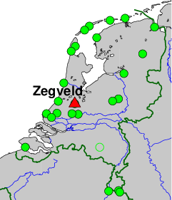
Integrated Geodetic Reference Station (IGRS), Veenweiden Innovatiecentrum, Oude Meije 18, 3474 KM Zegveld.
On-site contact: Sanneke van Asselen, Deltares
GNSS contact: Hans van der Marel, TUD/GRS
GNSS Instrument(s)
| Name | Marker | Receiver | Antenna | Operator | Network | Start date | End date |
|---|
| zegv | 13543M001 | SEPT POLARX5 | SEPCHOKE_B3E6 | DELTARES | IGRS | 2020-02-07 | |
Markers
| ID | Name | dX | dY | dZ | Instruments | Installed | Removed |
|---|
| 13543M001 | TOP OF IGRS MAST | 0.0000 | 0.0000 | 0.0000 | zegv | 2020-01-22T10:00Z | |
Pictures
Active instruments
Marker ID: 13543M001
Operator: TUD/CITG/GRS
Log file:
zegv00nld_20260514.log
Receiver
| Installed | week/d doy | Removed | week/d doy | Receiver type | S/N | Firmware |
|---|
| 2020-02-07T09:45Z | 2091/5 038 | 2020-02-07T20:40Z | 2091/5 038 | SEPT POLARX5 | 3046503 | 5.3.1 |
| 2020-02-07T20:40Z | 2091/5 038 | 2023-04-17T06:39Z | 2258/1 107 | SEPT POLARX5 | 3046503 | 5.3.2 |
| 2023-04-17T06:39Z | 2258/1 107 | 2026-05-14T12:42Z | 2418/4 134 | SEPT POLARX5 | 3046503 | 5.5.0 |
| 2026-05-14T12:42Z | 2418/4 134 | | | SEPT POLARX5 | 3046503 | 5.7.0 |
Antenna
| Installed | week/d doy | Removed | week/d doy | Antenna type | Dome | S/N | Height | Antenna calibration |
|---|
| 2020-01-22T10:00Z | 2089/3 022 | | | SEPCHOKE_B3E6 | SPKE | 5461 | 0.0000 | |
External Frequency
| Installed | week/d doy | Removed | week/d doy | Ext. Frequency type |
|---|
| 2020-02-07T09:45Z | 2091/5 038 | | | INTERNAL |
Notes
- 2020-01-22T10:00Z 2089/3 022 -
- The GNSS instrument mechanically connected to two 90 cm trihedral corner reflectors for
co-locating (In)SAR ascending and descending radar satellite tracks. The GNSS monument
itself consists of a SECO mount, on top of a 2.5 m heigh 8 cm diameter stainless steel
pipe, with a 35 cm square strudded footplate. On each side, a 90 cm corner reflector for
ascending and descending InSAR tracks is attached. 1.42 m below the GNSS monument a
GCP for LIDAR measurements (the top plate of the IGRS) is present. The whole assembly
is mounted on a concrete block fixed to 3 steel/grouted 11.5 long foundation piles to
sub-surface sand deposit. On top of the sand layer is a 8 m peat toplayer.
The top plate of the IGRS is 1.122 meter above the concrete block, the GNSS monument
is 1.416 m above the top-plate (LIDAR GCP).
- 2026-05-20T08:13Z 2419/3 140 - 2026-06-01T09:01Z 2421/1 152
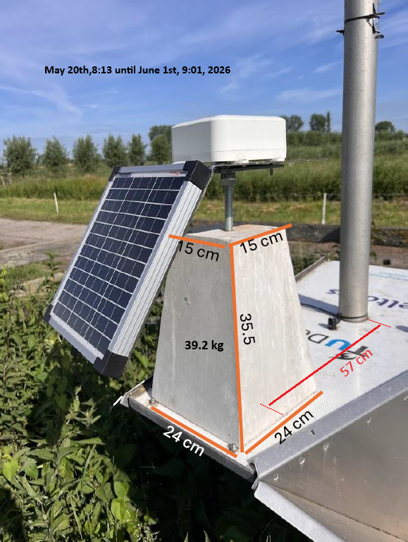
- Between May 20th and June 1st, 2026, a concrete block was placed, without authorization, on the top plate of the IGRS. For a picture
see concrete block with dimensions.
The tapered concrete block weighted 39.2 kg, with dimensions 24x24 cm at the bottom, 15x15cm at the top, and 35.5cm height.
It was placed on the top plate, South of the pole, with the center of the block at 0.57 m from the center of the pole.
The block was placed on the top-plate on May 20th, around 10:13 LT. On June 1st, around 11:01 LT the block was removed
and placed below the IGRS on the concrete foundation (where it doesn't affect the monument stability).
Measurements from an inclinometer, mounted on the pole just below the top-plate (at a height of about 1 m above the concrete
foundation), showed a tilt increase of roughly 0.035 deg, equivalent to approximately 0.6 mm displacement of the top-plate
towards the South during this period.
Measurements from an inclinometer at the top of the pole showed an inceased tilt towards South of 0.02 deg, equivalent to
approx. 0.7 mm (considering a pole length of 2 m).
Results from the inclinometer measurements are provisional and subject to change.
- 2026-06-01T09:03Z 2421/1 152 - 2026-06-01T09:35Z 2421/1 152
- Static load bearing and shaking tests were performed to obtain the response of the inclinometers and effect on the
stability of the IGRS construction.
For more information contact Hans van der Marel.